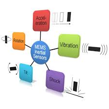
Interface for MEMS inertial sensors
Description
This patent disclosure describes an ASIC or other circuit to interface with MEMS inertial sensors such as vibratory MEMS gyroscopes and accelerometers, including in closed loop configurations. Closed loop configuration provides best performance in harsh environments. Techniques to improve the sensor interface performance are described, including techniques that allow for extending dynamic range of the MEMS actuation and detection signals, canceling coupling between electrodes in the MEMS module, and achieving fine phase tuning between sense and drive loops for improved demodulation.
Aspects
MEMS Sensor Interface Circuitry, This part of the circuit provides actuation voltages for sense and drive electrodes of the MEMS sensor, MEMS Sensor Drive (DRV) Loop, the drive loop 110 incorporates a phase shift 115A (DRV Phase) required to achieve an oscillation condition of a drive resonator 119 (including a mechanical element, e.g., a suspended mass) of the MEMS sensor, as well as automatic gain control 115B (AGC) to control the amplitude of oscillation of the mechanical element, MEMS Sensor Sense (SNS) Loop, the MEMS sensor includes a sense resonator 129 (including a mechanical element, e.g., a suspended mass), The Digital Processing Core: decimates and filters the output of the sigma delta modulators of both the drive and sense loops, and performs a final sense signal demodulation operation, Power Management: This block provides all required biasing currents and supply voltages to different circuit blocks. The Temperature Sensing System: This block senses the die temperature and converts it into a digital reading. Clocking PLL The PLL generates the master clock of the system
Patenting Status
Patent Granted
Status
Patented
Submit Your Intellectual Property Send Your Feedback


EgyptInnovate site is not responsible for the content of the comments